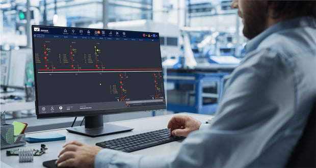
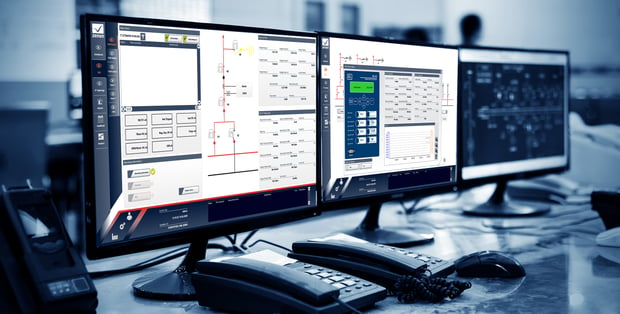
How does a substation single line diagram improve situational awareness?
A substation single line diagram improves situational awareness by showing operators the live state of the electrical network in one view. Powered, unpowered, grounded, and faulty sections are visible without reading individual status points. A clear diagram shortens response time during a fault. A poor one increases the likelihood of error.
Key takeaways
-
The single line diagram is the most visited screen in a substation automation system, and its design directly affects operator performance during normal operation and during faults.
-
Automatic line coloring removes the gap between the network's actual state and the operator's understanding of it.
-
Topological interlocking and safe command processing enforce switching rules in software, reducing the residual risk that remains when human checks are the last line of defense.
- zenon Energy Edition provides these capabilities within one platform for substation automation.
Why does single line diagram design matter?
An operator uses the single line diagram to understand what the network is doing right now, and to decide what action is safe to take next. During normal operation, that is a routine task. During a fault or a complex switching sequence, it becomes the most important task in the control room. If the diagram is slow to update, unclear, or inconsistent with the real state of the network, the operator loses time. In a switching sequence where a wrong action can damage equipment or endanger people, that time matters.
A single line diagram, sometimes called a one-line diagram, is a form of block diagram that graphically depicts the paths for power flow between entities of the system. The elements do not represent the physical size or location of the equipment. It is common convention to organize the diagram with the same left-to-right, top-to-bottom sequence as the switchgear it represents.
Three qualities separate a diagram that supports operators from one that merely documents the network. It must reflect the true topology, not a simplified approximation. It must update in real time as the network state changes. And it must present information in a hierarchy that lets the operator move from a system overview to a specific device without losing context.
What makes a substation HMI single line diagram effective?
An effective SCADA single line diagram gives the operator an accurate mental model of the network without requiring them to reconstruct it from raw data. The measure of success is not how much information the diagram contains. It is how quickly and confidently the operator can act on it.
In practice, building a dynamic single line diagram comes down to a small number of design decisions. It should show what is energized and what is not, based on the real topology. It should update automatically as breakers, switches, and protection devices change state. It should allow progressive disclosure, so that a system-wide view does not compete with the detail needed for a specific bay.
The same requirements apply whether the diagram covers a single substation or a fleet. A diagram that works for twenty bays may become unusable at two hundred if the hierarchy is not structured to handle it.
Two capabilities distinguish a diagram that supports operators under pressure from one that merely documents the network. Automatic line coloring shows the state of the system at a glance. Topological interlocking and safe command processing keep unsafe actions from reaching the field. The sections that follow explain what each contributes, and why the difference shows up most clearly in the minutes after something goes wrong.
How does automatic line coloring work?
Automatic line coloring improves situational awareness by showing the state of every line, breaker, and device in a single view. The technique is also known as topological coloring, because the colors are derived from the network's topology rather than from individual device status. Powered, unpowered, grounded, and faulty sections appear in different colors, so the operator understands the network condition without reading individual status points.
Without ALC, the operator reads raw status data and builds the picture mentally. With ALC, the picture is already there. After a fault, several devices change state at once. Without ALC, the operator works through the status points individually to establish what happened. With ALC, the resulting state is visible immediately, so the operator can begin deciding on a response sooner.
The value of ALC depends on the accuracy of the electrical model behind it. If the model reflects the true topology of the substation, the coloring can be trusted. If the model is incomplete or out of date, the coloring can mislead, which is worse than no coloring at all. For this reason, the electrical model and the diagram must be maintained together, not as separate tasks.
How does topological interlocking prevent unsafe switching?
Topological interlocking prevents unsafe switching by checking every command against the live state of the network before it is executed. If the action would create an unsafe condition, such as closing onto a ground, the command is blocked.
In a conventional substation, switching rules are documented in procedures and enforced through training and supervision. Topological interlocking enforces those same rules in software, before the command leaves the control room. Because the logic is based on live topology, it accounts for the actual state of the network rather than the expected state.
This does not replace operator judgment. It adds a safety layer that catches sequences which would otherwise require manual verification across multiple screens. For utilities managing complex switching operations, that layer reduces both the time needed to confirm a sequence is safe and the residual risk that remains when supervision is the final check.
How does safe command processing prevent operational errors?
Safe command processing adds verification to every switching action. Select-before-operate ensures that a device is controlled by only one operator at a time. Revision mode places the system in a defined state for testing or commissioning while the substation remains in operation. Lock out, tag out prevents equipment from being re-energized while maintenance is in progress. Role-based access determines who can perform which actions.
Select-before-operate addresses a specific and common failure mode: inconsistent operation from concurrent operators. Before any command is issued, the device is allocated through an initial request. During that request, the system checks whether the device is already allocated by another operator, such as another remote client, a test system, or a local operator on site. Only if the device is not otherwise busy or allocated will the selection succeed and the device be ready to receive operational commands.
Revision mode and lock out, tag out address the safety of work being performed on the system. Revision mode allows a section of the substation to be placed in a defined state for testing, without removing the rest of the substation from service. Lock out, tag out ensures that equipment under maintenance cannot be energized from the control room, even if a command is issued in error.
Role-based access determines which operators can perform which actions, so that command privileges match operational responsibility. A field technician and a control room operator do not have the same permissions, and the system enforces that distinction at the point of command. Every action is recorded in the sequence of events log, which supports both incident investigation and regulatory reporting.
How does zenon support an intelligent substation single line diagram?
zenon Energy Edition provides the SCADA capabilities needed for an intelligent substation single line diagram, including automatic line coloring, topological interlocking, and safe command processing.
These capabilities depend on the same electrical model. Automatic line coloring, interlocking, and safe command processing all reference the substation topology, so the diagram and the model behind it are maintained as one.
zenon connects to protection and control devices using the protocols used in substation automation, including IEC 61850, DNP3, and IEC 60870-5-101/104. The same platform that drives the single line diagram also handles alarm management, event logging, disturbance record collection, and gateway communication to higher-level control centers. For utilities that need advanced diagram functionality within the substation, zenon provides these capabilities in a configurable SCADA environment.
FAQs about substation single line diagrams
-
A substation single line diagram is a schematic that shows how power flows between equipment inside a substation. It represents a three-phase system with a single line and is the primary screen operators use to monitor and control the site.
-
A single line diagram shows electrical relationships between equipment using one line per circuit. A schematic diagram shows individual conductors and detailed circuit information. They serve different purposes and are not interchangeable.
-
A dynamic single line diagram updates automatically as the state of the network changes. Breakers, switches, and protection devices are reflected in real time, so the operator sees the current configuration rather than a static drawing.
-
Common symbols include circuit breakers, disconnectors, transformers, busbars, generators, grounding points, and instrument transformers. Each represents a piece of equipment and its function in the power flow path.
-
The operator's understanding of the network becomes wrong, and switching decisions made on that understanding become unsafe. Keeping the electrical model accurate is what makes the diagram reliable.
-
A single line diagram typically covers one substation. Fleet-level views use a different representation, such as a geographic overview or a system schematic, rather than one diagram per site.
-
Because a three-phase power system, which physically has three conductors, is drawn as a single line. This keeps the diagram readable while still showing how equipment is connected.
-
A single line diagram represents a three-phase circuit with one line. A three-line diagram shows all three phases separately. Single line diagrams are the standard for substation overviews because they stay readable at scale.
-
Start with topology: what is connected to what. Then read state: which sections are energized, grounded, or isolated. Then read device status: which breakers and switches are open or closed. Automatic line coloring shows state directly on the diagram, which removes the need to check status points individually.
-
Automatic line coloring, also called topological coloring, shows the electrification state of lines, breakers, and other devices in different colors based on the substation's electrical model. Powered, unpowered, grounded, and faulty sections are distinguished at a glance.
-
State changes update in real time through the SCADA system. The underlying electrical model should be reviewed whenever the physical configuration changes, such as after a refurbishment, an extension, or a protection upgrade.
Substation Automation Success Stories
-
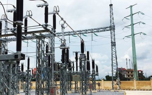
Energy & Infrastructure, Vietnam, Substation Automation Empowering local ownership of energy infrastructure at EVN Hanoi (Vietnam)
Read moreLocal COPA-DATA distributor PETROLEC has been instrumental in helping EVN Hanoi to implement a new control system based on zenon automation software for more than 30 of its 110kV substations.
-
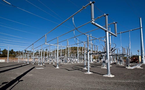
Energy & Infrastructure, Australia, Network Control, Substation Automation, Human Machine Interface (HMI) COPA-DATA energizes Powerlink Queensland’s HMI systems (Australia)
Read moreQueensland’s high-voltage electricity transmission network provider chose zenon to carry out a major upgrade to its HMI. COPA-DATA’s commitment to ‘parameterization instead of programming’ enabled a cost-effective and highly-functional solution without the need for an expensive recommissioning effort.
-
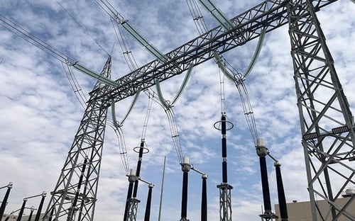
Energy & Infrastructure, Saudi Arabia, Network Control, Substation Automation Saudi Electricity Company: Lighting up Arabian Nights (Saudi Arabia)
Read moreWith the implementation of COPA-DATA's hardware-agnostic zenon software platform, SEC's Frusyah 110/13.8 kV substation was transformed with a state-of-the-art automation solution by System House Factory for Electric Panels Co. (SEP). Implemented within a few weeks, this innovative system ensures reliable operation and simplified maintenance for a seamless power supply.
Choose zenon for all your substation automation needs
Managing or entering the digital substation market can feel overwhelming. Luckily, zenon can simplify this process. zenon is designed for flexibility, meaning it is optimized for on-site and remote maintenance, whether you need to take a manual approach or focus on automation. For more information, contact COPA-DATA today!